Extending the Environment Monitor with Blynk
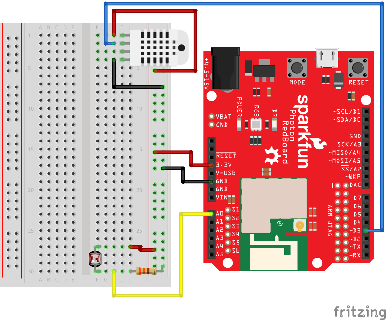
This tutorial builds off of Experiment 6: Environment Monitor of the Sparkfun Inventor’s Kit for Photon Experiment Guide. As you will recall, your homework for today’s class was to complete Experiment 6 up to “Part II: Posting Environmental Data to data.sparkfun.com.” Because data.sparkfun.com and its associated data logging engine Phant are currently not allowing the creation of new data streams, we have to look to other IoT cloud platforms.
We’ve already made some use of Particle’s console (and its Publish/Subscribe i/o schema). Let’s explore another one! There are many options to choose from, each with its own unique feature-set and pros/cons, including:
In this tutorial, we will use Blynk.
What is Blynk?
Blynk is an IoT platform with iOS and Android apps that enables users to control Photons, Arduino, Raspberry Pi and similar devices over the Internet.
It is comprised of three components:
-
Blynk App - mobile applications that allow you to interface with your IoT devices.
-
Blynk Server - an open source cloud-based server that brokers communication between the smartphone running the Blynk App and the IoT device(s).
-
Blynk Libraries - that run on the IoT device, sending data from the device to the Blynk Server and receiving commands from the Blynk App, relayed through the Blynk Server.
Part I - The Blynk App
-
If you haven’t already, you will need to download and install the Blynk App:


-
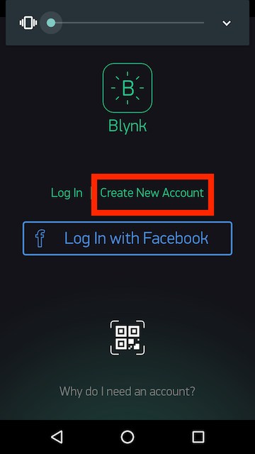
Launch the Blynk App and Create a Blynk Account
After you download the Blynk App and open it, you’ll need to create a New Blynk account. (Note: This account is separate from the accounts used for the Blynk Forums, in case you already have one.)
Blynk recommends using a real email address “because it will simplify things later” – in particular, you will be able to reset your password as well as receive application auth tokens by email that you can cut-and-paste into the Particle online IDE.
-
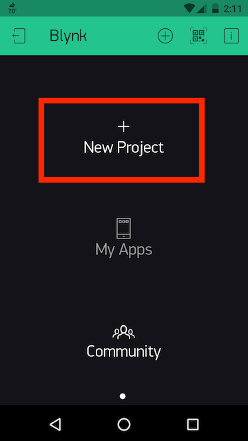
After you create your account, you will be able to create a + New Project:
-
Give your project a name (e.g. “Enviro-Monitor”).
-
Under “Choose Device”, scroll until you find “Sparkfun Photon Redboard”:
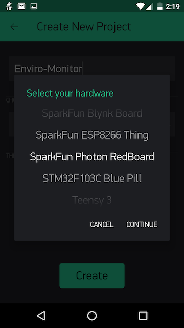
and then press “Continue.” -
Leave the Connection Type as “WIFI” (but note that you use several other protocols depending on your device’s capabilities).
-
Press the “Create” button. This will cause the Blynk App to send you an email with your Auth Token. Check your email to verify that it has been sent.
An Auth Token is a unique identifier which is needed to connect your hardware to your smartphone. Every new project you create will have its own Auth Token. You’ll get an Auth Token automatically on your email after project creation. You can also copy it manually.
Part II: Add Widgets to your Blynk App Project
The Blynk App contains an impressive range of pre-built widgets that you can use to represent data sent from your IoT device and/or control your IoT device. For example, you may want to add a button to the graphical user interface that turns on an LED or trips a relay switch.
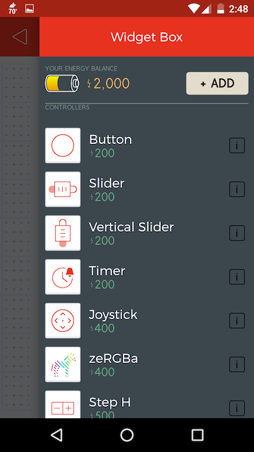
Note that you have a “Energy Balance” of 2,000 credits, and that each widget “costs” a finite amount of credits. You can purchase additional credits by purchasing energy packs by pressing the “Add” button. As we prototype, however, we can make do with our base allocation and “recycle” credits back to our Energy Balance when we’re done with this project.
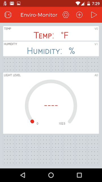
In this tutorial, we want to create a display for the temperature (in degrees Fahrenheit), the % humidity, and a gauge for the light levels, as illustrated below:
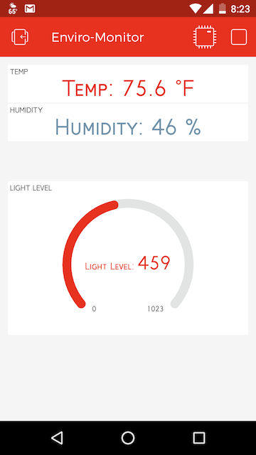
Let’s build our interface!
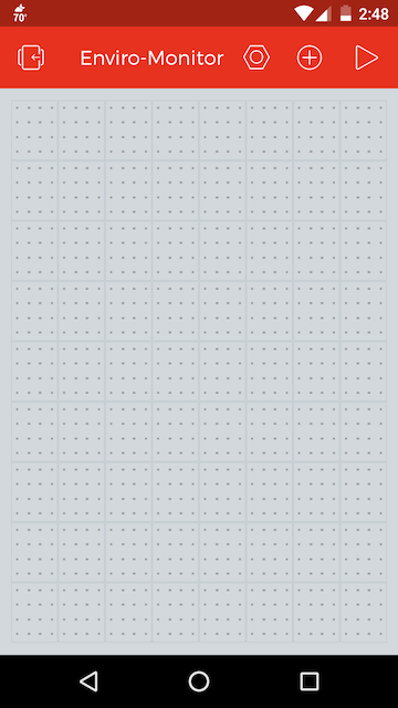
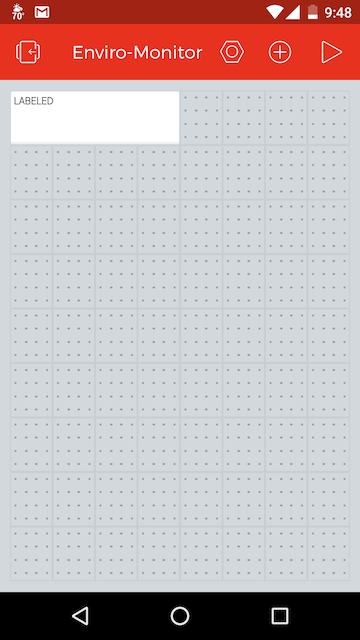
At the completion of Part I, you should be looking at a blank Blynk App canvas:
-
Let’s begin by adding a widget to the canvas. Click on the ⊕ icon at the top of the canvas to pull up the widget list.
-
Scroll down until you see the “Labeled Value” widget and tap it to add it to the interface.
-
Tap on the newly added “Labeled” field on the canvas to access its settings screen:
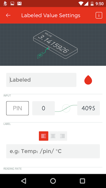
- Where it says “Labeled”, change the text to “Temp”.
- You can change the text color by clicking on the red teardrop.
- Under Input, we’re going to send our data from the Photon to a “Virtual Pin” so click on the “PIN” button and choose Virtual V0 and then click “Continue.”
- We then need to set the range of expected data. Since we can reasonably assume that ambient air temperature will range from -20 to 130 degrees, you can enter these values for MIN and MAX.
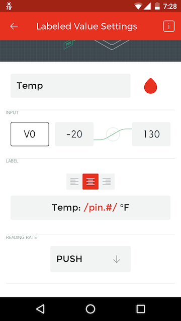
- Under Label, you will use the following syntax:
Temp: /pin.#/ °Fto specify the degrees with a resolution of .1 degree (e.g.Temp: 45.3 °F). See Labeled Value Formatting Options for more information. - Finally, for Reading Rate, choose “PUSH” (e.g. we want the data to update whenever the Photon “pushes” the data to the cloud.)
The results should look like this:
-
Press the back arrow to return to your canvas. Your canvas should now have a single element, a Temp field as illustrated below.
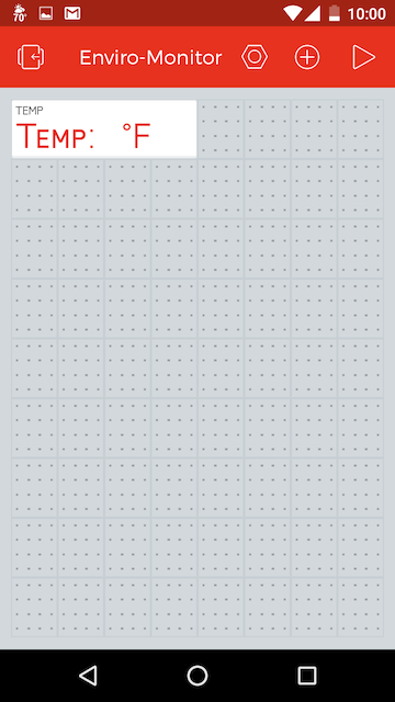
-
Click on the ⊕ icon again at the top of the canvas to create a second widget. Note that your Energy Balance has been reduced by 400 credits, the “cost” of a Labeled Value widget.
-
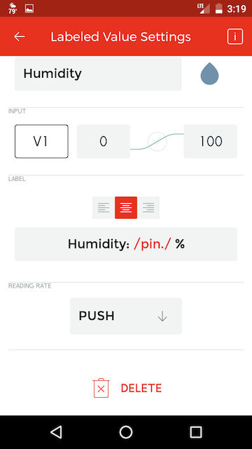
Add a second “Labeled Value” widget for the % Humidity to your interface. Assign it to Virtual Pin 1 (V1) with a display syntax of
Humidity: /pin./ %. It can also be set to use PUSH for a Reading Rate.
-
Finally, add a Gauge widget to the application canvas.
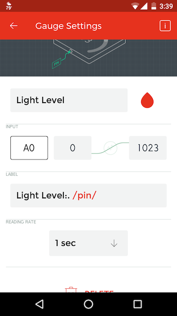
You can adjust the position and size of your widgets by pressing and holding on them. Drag to reposition and use the handles to resize.
You are now ready to make the modifications to your Photon’s Arduino code to connect to the Blynk App and Server.
Part III: Modify your Code
Recall that the code from Experiment 6 took temperature and humidity readings from the RTH03 sensor and light readings from the photocell every 1.5 seconds. The onboard LED (attached to pin D7) would blink every time a reading was taken from the sensors. And the data from these sensor readings was sent over USB serial to your attached computer. The whole point of the IoT, however, is that devices can operate wirelessly and remotely.
In this exercise, we will modify the Experiment 6 code so that instead of simply writing the data to serial, the Photon will send the data to the Blynk Server enabling its display on the Blynk App dashboard we created in Part II above.
-
Go into the Particle online IDE and find the Particle app that you created when you completed Part I of Exercise 6.
-
Select all of the code in that app and copy it. Next, create a new app called “EnvironmentalLoggerBlynk”, pasting the code into the new app.
- Note that the libraries associated with a particular project DO NOT get copied over when you cut-and-paste code between projects in the Particle online IDE. As a consequence, you will need to re-include the RHT03 library:
- Delete the top two lines of the code you’ve copied over:
// This #include statement was automatically added by the Particle IDE. #include <SparkFunRHT03.h> - Go to the Libraries section of the online IDE and search for “RHT03”.
- Click on “SparkFunRHT03” to select that library and then click on the blue “Include in Project” button.
- Under “Which App?”, select the project that you just created and click “Confirm”.
- Delete the top two lines of the code you’ve copied over:
-
Also add the “blynk” library, which will enable functions for communication between your Photon and the Blynk ecosystem.
- Your code should now have both of the following libraries included in the code
#include <SparkFunRHT03.h>
#include <blynk.h>
and listed under the Particle app’s “Included Libraries” list in the Code panel.
- Now we can add in the code necessary to interact with the basic functionalities of the Blynk library. For more information on these functions, visit the Blynk Firmware Documentation.
Find your Auth Token from Part I, #7 and add it to the declarations above thevoid setup()function:char auth[] = "YourAuthToken"; - Inside the
void setup()function, on the last line before the closing }, add:Blynk.begin(auth); // initiate Blynk libraryMore info on Blynk.begin()
This function initiates the Blynk library and establishes a connection to the Blynk server. - At the top of the
void loop()function, add:Blynk.run();More info on Blynk.run()
This function will enable Blynk’s access (read and/or write) to the digital and analog pins of your Photon if you have configured them in the Blynk App. -
Finally, in the section of the
void loop()after the calculation ofhumidityandtempFand before the section ofSerial.print()section, add the following lines:Blynk.virtualWrite(V0, tempF); //virtual pin 0 will be the temperature Blynk.virtualWrite(V1, humidity); //virtual pin 1 will be humidityThese functions will “write” the values of the tempF and humidity variables to the Blynk server and relay them to the corresponding widgets on the Blynk App canvas. More info on Blynk.virtualWrite()
-
Verify and then flash the code to your Photon Redboard.
- Finally, in the Blynk App, click the “play” icon in the upper-right of the Blynk mobile app to switch from EDIT to PLAY mode.

You should see data appear in the App, updating regularly.