GPIO
GPIO stands for ‘General-Purpose Input Output’, and is a library that allows us to interact with the pins on our board. Because the majority of this class will be developed in python, we’ll be installing python Rpi.GPIO and other packages.

Type:
sudo apt-get update
this will update the current OS. Next run
sudo apt-get install python-rpi.gpio
This will install the python GPIO package. This package will allow us into interact with the pins on the board ( which we’ll solder on later).
To check that it is installed correctly, type
python
you should then be dropped into the python interactive shell. We can then run
import RPi.GPIO as GPIO
To check that package is present, type
GPIO.RPI_REVISION

Since we’ve ‘ssh’ed’ into our rasberry pi’s, we’ll have to use nano or some other text editor to write our code. My preferred text editor is nano, though vim will also work on the raspberry pi’s out of the box.
We’ll start a new script by navigating to a folder we’d like to work out of and running
nano gpio_pi.py
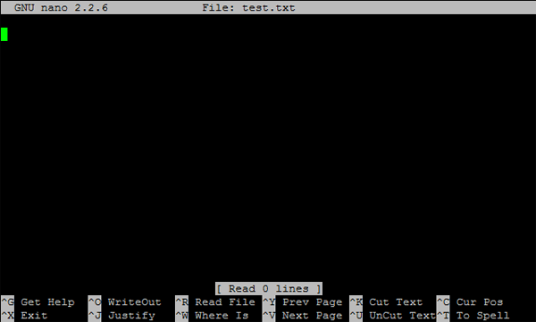
We should now have a text editor in front of us start writing our GPIO code.

We’ll start by importing the GPIO library and giving it a name, in this case ‘GPIO’. The ‘as GPIO’ portion just allows us to reference the library by writing ‘GPIO’ instead of ‘RPi.GPIO’ every time. We’ll also import the ‘time’ library (pre-installed), to give us some time controls over the actions.
import RPi.GPIO as GPIO
import time
Our goal is a basic hello world, turning an LED on and off, so we’ll first define a variable for the pin that we want to use to communicate with the LED by setting the variable ledPin to pin 23.
ledPin = 11
How do we know which pin is number 11? We’ll have to set a pin-mode.
Next let’s set the pin-mode, which will allow us to reference to pins on our boards. There are two pin-modes: ‘BMC’ and ‘BOARD’
While the GPIO library is relatively straightforward to use, though the layout of the pins, and how to reference them are a bit confusing at first.
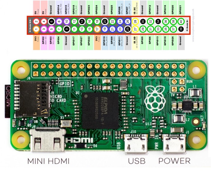
Using the ‘BOARD’ pin-mode is the most straight-forward, as the pins count left to right, from the top of the board to the bottom. They are referenced by the circles in the image below.
The ‘BMC’ pin-mode, option means that you are referring to the pins by the “Broadcom SOC channel” number, these are the numbers after “GPIO” in the green rectangles around the outside of the below diagrams. s

For this tutorial we’ll stick with BOARD.
We’ll specify that we want to use BOARD with
GPIO.setmode(GPIO.BOARD)
Lastly, we’ll have to set our GPIO pins with ‘GPIO.setup’. This will communicate to the board that we want to either pull in data from the pin or output data from the pin. In this case, we’ll output data, since we’ll be turning an LED on
GPIO.setup(ledPin, GPIO.OUT)
We’ll also start out by turning on the LED. We can interact with the pin we defined above with ‘GPIO.output’. Here we’re referencing the pin, and setting the output of the pin to high, much like we would with the Particle Photons. This will output 3.3v to pin 23
GPIO.output(LedPin, GPIO.HIGH)
We can start to set up our program much like we would with the Photons, with a “setup” function and a “loop” function. Since there is no set syntax for python and no “special functions”, we could call these functions anything we want, but for now we’ll stick with “setup” and “loop”
We take the setup code that we’ve writen above, and define our setup function as such
def setup():
  GPIO.setmode(GPIO.BOARD)
  GPIO.setup(LedPin, GPIO.OUT)   # Set LedPin's mode is output
  GPIO.output(LedPin, GPIO.HIGH) # Set LedPin high(+3.3V) to turn on led
Next, we’ll define our “loop” function to turn the LED on and off. Much like we did with the initial output command in the setup funciton, we can do the same in the loop function. In our loop function, we’ll define a while-loop and set it to “True” (which by default is always true). Next we’ll write to the pins with GPIO.output, and set the output to “low” and “high”. We’ll also define a “sleep time”.
In total this function says while True (all the time), set pin 23 to high (led on), wait 1 second, set pin 23 to low (led off)
def loop():
  while True:
    GPIO.output(LedPin, GPIO.HIGH)  # led on
    time.sleep(1)
    GPIO.output(LedPin, GPIO.LOW) # led off
    time.sleep(1)
Lastly, we’ll define a function that will allow us to turn the LED off and close the connections when the program is killed. We can do this by setting pin 23 to low (off), and calling GPIO.cleanup() which kills all of the connections to the board
def destroy():
  GPIO.output(LedPin, GPIO.LOW)   # led off
  GPIO.cleanup()                  # Release resource
This is an important part to Raspberry Pi programming, unless you code for situations with cleanup, any ports which are in use at the time of an error or Keyboard Interrupt will stay set exactly as they were, even after the program exits. You can imagine the obvious caos and confusion when you restart your script again.
Lastly, we can start our program by setting name equal to ‘main’ and calling the functions we defined above. Below ‘if name == ‘main’, we’ll call our setup function. Next we’ll try to run the loop function. This function will run until there is a KeyboardInterrupt (Ctrl + C) or the program is killed. When its killed, we’ll call our destroy function, turning the LED off and closing the connections.
In total, here is our full code:
import RPi.GPIO as GPIO
import time

LedPin = 11    # pin 11

def setup():
  GPIO.setmode(GPIO.BOARD)
  GPIO.setup(LedPin, GPIO.OUT)   # Set LedPin's mode is output
  GPIO.output(LedPin, GPIO.HIGH) # Set LedPin high(+3.3V) to turn on led

def loop():
  while True:
    GPIO.output(LedPin, GPIO.HIGH)  # led on
    time.sleep(1)
    GPIO.output(LedPin, GPIO.LOW) # led off
    time.sleep(1)

def destroy():
  GPIO.output(LedPin, GPIO.LOW)   # led off
  GPIO.cleanup()                  # Release resource

if __name__ == '__main__':     # Program start from here
  setup()
  try:
    loop()
  except KeyboardInterrupt:
    destroy()
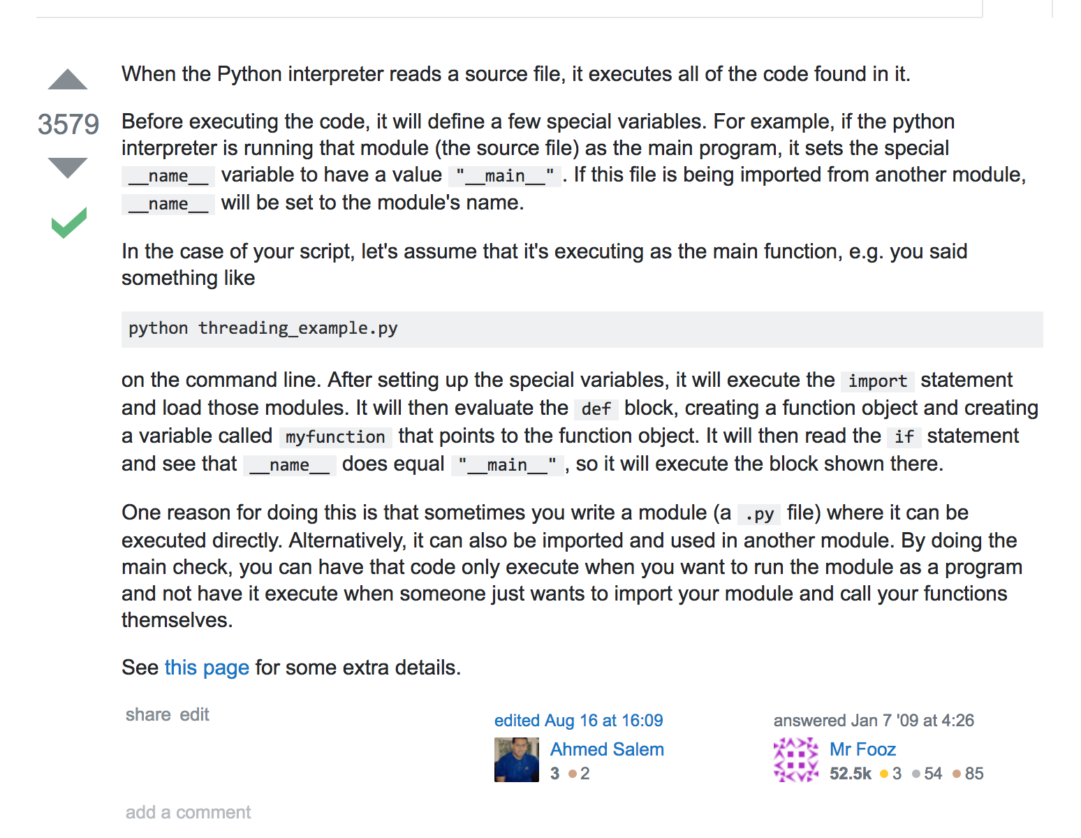
Addendum: What is “if name == ‘main’”???
